- Company: SEMA Construction, Inc.
- Industry: Transportation
- Location: Denver, Colorado
- Expected Completion Date: September 1, 2014
- Project Website
The Peoria Crossing Design-Build Project represents an unprecedented collaboration between the (Owners): City and County of Denver (CCD) and the City of Aurora (COA) and the additional (Stakeholders): Regional Transportation District (RTD) and Colorado Department of Transportation (CDOT), to enhance the safety of the traveling public and operational efficiency of Peoria Street.
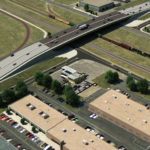
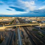
Peoria Crossing is an important connection between Denver and Aurora that was hampered by the at-grade crossing of the Union Pacific railroad (UPRR) tracks. SEMA Construction, Inc. and Parsons Brinckerhoff, Inc. (Project Team) provided a design-build solution involving the construction of a grade separated structure elevating Peoria Street over the UPRR yard and the future RTD East Rail Line.
The Project Team included numerous value added benefits to the project, representing over $3.6 million in direct project cost savings. This project was completed nine months ahead of the original completion date.
What impact does this project have on America?
The Peoria Crossing Design-Build project has a significant impact on the multi-modal traveling public in Denver, Colorado, in addition to the Union Pacific Railroad. Peoria Street is a key north-south arterial roadway through the cities of Denver and Aurora. As a major employment corridor, it provides access to and from several key regional facilities, including Denver International Airport, Interstates 70 and 225, Colfax Avenue, transit stations, emergency service providers, the Anschutz Medical Campus, universities, schools, local business, and community service organizations. Peoria Street is an active crossing for the UPRR with up to 60 railroad gate closures occurring each day, impacting the approximately 32,000 vehicles that cross the tracks daily. The number of trucks that use the street to access adjacent industrial properties further exacerbate traffic congestion on Peoria Street.
The new Peoria Crossing Bridge is a major infrastructure improvement that solves many of the congestion and access issues that plagued this area. It also serves as a gateway to the Peoria corridor, is an important part of realizing each city’s vision, and is a cornerstone for future redevelopment.
What interesting obstacles or unusual circumstances did you overcome to complete the project?
The grade separated structure constructed to elevate Peoria Street over UPRR and future RTD East Rail Line presented a unique obstacle for the team that required a resolution driven by innovations in technology. The Bridge structure had to totally clear span the UPRR right-of-way, which was geographically adjacent. This was also to be completed in an accelerated schedule in order to allow for on time testing of the RTD East Rail Line.
The Team determined that one of the greatest challenges they would face in design and construction would be obtaining approval from UPRR for placing a substructure element within their ROW. The Team also evaluated the potential costs and risks associated with the Project schedule pertaining to obtaining approvals from UPRR. This lead to the final design that did not propose any structure component within the UPRR ROW and provided minimum clearance throughout this area. This approach streamlined UPRR review and approval and eliminated any schedule impacts that would otherwise be caused.
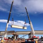
The Team innovated a three-span; 560 ft. bridge comprised of five girder lines of trapezoidal precast post-tensioned concrete U-girders. This design provided a center main span of 240 linear feet, which placed all substructure elements out of UPRR ROW. Through the Team’s experience on other projects, it was determined that smaller depth girders, versus what was originally planned, would meet the design requirements, so the girder depth was reduced from 96” to 84”, this also reduced the embankment height. While the costs could potentially be reduced by having a bridge structure with smaller spans, in the end, with all costs accounted for including the cost of permanent ROW from UPRR; the additional cost savings was negligible.
This design also enhanced the visual aesthetics of the bridge, which was important to overall renovation of this area that would later become the primary transfer station between the I-225 Light Rail Line and the DIA Commuter Rail Line. The new Bridge has a slender appearance with smooth arching girders and a pedestrian plaza with a rail transit orientated theme in the concrete walkways. The bridge incorporates clean and simple lines utilizing precast concrete U girders as the primary support for the bridge. These girders form the smooth, arching Bridge and are the prominent bridge component. The overall proportions of the Project focused mainly on the Bridge and structure itself. The span length of the Bridge is broken into three different spans, with each end span shorter than the larger middle span. The shorter spans are 165’ on the south and 145’ on the north. This proportion of approximately 1:1.5:1 of the main structure provides a balanced proportion for the bridge. Smaller piers are used to give the bridge a lighter look and a profile that is focused on the superstructure of the bridge to highlight the overall span.
What dangers and risks did you encounter, and describe any extraordinary methods used to keep workers safe?
There was a significant risk to the project that the team faced. That was the concern the Owner had with this project was that the original geotechnical evaluations of the existing underlying soil conditions predicted several inches of settlement. The risk of settlement under the embankment and retaining walls presented a significant concern for the long-term life of the project. There was a predicted risk of as much as eight inches of settlement, and by the technical specifications, the allowable settlement criteria for this project was reduced from the allowable tolerances the Project Team was typically required to meet.
The Team’s approach to the overcoming the technical settlement criteria was to preload the center of the roadway approaches. This was possible due to the width of the roadway prior to the construction of the MSE Walls. By preloading the existing soils with embankment approaching the height of the final embankment for a mandatory settlement period of three months, the Team was able to consolidate the majority of the underlying soils. This allowed the bulk of settlement to occur prior to the construction of any additional element on the embankment and walls including the moment slabs and concrete pavement.
Exhaustive safety pre-planning and the implementation of an on-site safety team resulted in a safety program that exceeded industry standards. The Project Team, including a Safety Manager and Safety Officer, developed a site-specific Safety Management Plan (SMP) prior to the onset of the Project. The SMP outlined job-specific safety regulations, addressed potential hazards and detailed the personal protective equipment required. Although team members received in-depth safety training upon employment, the Project Safety Manager conducted site-specific safety training relative to each task of construction. To further ensure jobsite safety, daily safety briefings and weekly safety “Tool Box Talks” were required for the Team every week during the project.
Health, Safety, Environment & Quality (HSE&Q) processes were integrated to ensure systematic recognition and reduction of risks to the team. Subcontractors were also required to achieve excellence in HSE&Q.
The Project specific Health and Safety Plan (HASP) addressed the identified Hazardous Material (RHM) to ensure the field personnel were adequately trained and prepared to address them. The Team worked side-by-side with the Owner and RHM Manager to ensure that safety of all workers and the public was the number one priority!
The safety of pedestrians was a critical concern during the Project. To ensure their safety, SEMA implemented the following procedures to minimize these safety risks: access through the work zone was fenced with a warning barrier, the sidewalk was always maintained and clean with signage clearly indicating the pathway, and construction traffic was separated from pedestrian paths. SEMA coordinated with RTD to temporarily move the two on-site bus stops outside of the construction zone for the duration of the Project.
SEMA provided regular communications to CCD/COA emergency providers to keep them appraised of lane shifts and construction activities so that they could reroute accordingly, therefore preventing safety hazards.
How did you leverage new technologies to work faster and reduce waste?
SEMA leveraged technology, that was new to CCD, to overcome a major challenge with this project. CCD was averse to the use of precast MSE retaining walls, which the Project Team had proposed as a part of the solution to mitigate the settling issue, and it was one of their Alternative Technical Concepts (ATC) representing a cost savings of $2,474,000. CCD had never allowed precast MSE walls and would traditionally only approve cast-in-place retaining walls.
In addition to their ability to mitigate the settlement issue, the MSE Walls represented a significant aesthetic element of the Project and were also a necessity in clear-spanning the UPRR ROW. The walls associated with the approaches to the bridge are the largest single visual element within the Project. The panels were staggered vertically and the faces were broken up into two distinct wall textures to help reduce the massive look of the walls. The lower 12’ of walls are a running bond masonry block with a quarry face stone finish. This finish adds a more human scaled element to the wall, adds interest through texture and helps to reduce the potential for graffiti. The top of this 12’ high band has a cap cast into the panel creating a bold horizontal band along the length of the wall. The upper portion of the wall above 12’ has clean, horizontal lines at 2’-6” OC that works within the MSE panel pattern. The top of the wall has a cast in place cap with a 2’-6” exposed face and a 6” overhang. This cap and overhang adds another level of detail to the wall and creates a shadow line anchoring the top of the wall. The other added feature of the walls is the vertical pilaster that occurs every 50’ along the length of the walls. This 5’ wide pilaster helped to add additional human scale to the large structure and created a rhythm that helped to break up the overall length of the walls.
The Team’s extensive experience and success with precast MSE walls on other projects around the country convinced the Owner that this was another vital solution to the settlement issue. Once SEMA began to self-perform the installation for the 30 ft.-high MSE Walls, monitoring points were installed so that additional wall settlement could be examined on a bi-weekly basis. Upon completion of the MSE Walls, the Team found only a slight amount of settlement, 1-1/4 inches, in lieu of the predicted eight inches of settlement.
Although the Team believed the predicted eight inches of settlement occurred, their problem-solving design and construction solutions like preloading the area prior to construction, as well as the timing in which the walls were constructed, accelerated the predicted settlement ahead of schedule without risk to the MSE wall system. This allowed the Team to remove the settlement period risk from the construction schedule.
The Materials Management Plan (MMP) was the key to reducing waste on this Project. As required in the Categorical Exclusion Determination, CCD had completed a Phase I and Phase II Site Assessment on the Project and has completed a Materials Management Plan with Pinyon Environmental, Inc. (Pinyon).
In accordance with the Project’s pre-approved MMP, the Project Team managed hazardous waste mitigation pertaining to the 11 buildings demolished during construction. Denver Public Works partnered with CCD’s Department of Environmental Health on the sampling/investigation process and worked with their on-call abatement contractors to abate these buildings which all contained some sort of hazardous materials, mostly asbestos.
The construction operations were performed in a manner that minimally affected local communities with construction noise, construction vehicles, and environmental side effects. The Greenprint Denver strategies minimized emissions from construction vehicles. Visible dust emissions were controlled through the implementation of a fugitive dust control plan, a dedicated 4,000-gallon water truck, and timely stabilization of disturbed areas. SEMA also complied with the Denver noise ordinance to reduce noise pollution.
The Project Team incorporated additional Greenprint Denver strategies, which emphasized a sustainable community through the use of environmental strategies. These project requirements included: maximizing the reuse of materials generated on-site by minimizing the need for the removal of onsite earthwork, thereby minimizing the off-site borrow materials and reducing environmental impacts associated with truck hauling; recycling existing pavement materials to be reused in the Project which reduced imported materials and provided for a maintenance free surface on designated remaining parcels of land that were not incorporated into the Project, i.e. asphalt millings were reused from the Project in locations where appropriate reducing the amount of materials hauled to landfills; the Project Team substitution of fly ash for ASTM C150 cement in concrete.
Added innovations in technology included selecting concrete pavement over asphalt pavement to provide the project with a higher quality and future low maintenance cost for the pavement on the new project alignment. Additionally, the majority of curb returns were designed to accommodate turning movements of the WB-67 tractor trailer to improve traffic flow and minimize future maintenance costs.
